AC Servo Motor, 380V 5.5kW Servo Drive For Cardboard Cap Molding
Machine
Servo Drive For Cardboard Cap Molding Machine
AC Power 5.5KW
Single/Three Phase 380V
Modbus / CanOpen / EtherCAT
Location / Speed / Torque Control Mode
2500 pulse incremental + Hall encoder;
Products Description
| Product Name | Servo Drive For Cardboard Cap Molding Machine |
| Brand | Vector |
| Model No. | VEC-VC-01233H-M-E |
| Power | 5.5KW |
| Input/Output | Pulse / Analog |
| Voltage | 380V |
| Phase | Single/Three Phase |
| Rated Current | 12A |
| Communication Protocols | Modbus / CanOpen / EtherCAT |
| Encoder | 2500 pulse incremental + Hall encoder; |
| Pulse Command Input | Pulse Type | Differential input,Open collector |
| Frequency Range | Differential input:0-500kHz,pulse width greater than 1us
Open collector: 0-300kHz,pulse width greater than 2.5us |
| Pulse Mode | pulse + direction; AB pluses; CW+CCW; |
| Analog Input | Voltage Range | -10V to 10V |
| Input Impedance | 10kΩ |
| Maximum Frequency | 1.5kHz |
| DI/DO Interface Type | NPN/PNP |
| Communication | Modbus/CANopen/EtherCAT |
| Location Mode | Command Input Method | Pulse Command
Internal Planning Position
Plan by target position, speed, acceleration and deceleration
time
Trapezoidal speed curve
Cubic speed curve
Absolute / relative command mode |
| Instruction Smoothing Mode | Low Pass Filtering / Median Filtering |
| Electronic Gear Ratio | N/M;(M=1~2147483647,N=1~2147483647) |
| Torque Limit | Internal Torque Limit / Analog Torque Limit |
| Feedforward Compensation | Speed Feedforward / Torque Feedforward |
| Torque Compensation | Fixed Torque Compensation / Analog Torque Compensation /
Automatic Torque Compensation; |
| Speed Contol Mode | Command Input Type | Pulse Frequency / Analog / Internal Planning Speed |
| Speed Control Range | 1~max speed |
| Bandwidth | 1kHz |
| Torque Limit | Internal Torque Limit / Analog Torque Limit |
| Instruction Smoothing Mode | Low Pass Filtering / Median Filtering |
| Feedforward Compensation | Torque feedforward |
| Torque Compensation | Fixed Torque Compensation / Analog Torque Compensation /
Automatic Torque Compensation; |
| Torque Control Mode | Command Input Type | Internal Torque Reference / Analog Control Torque |
| Torque Compensation | Fixed Torque Compensation / Analog Torque Compensation /
Automatic Torque Compensation; |
| Speed Limit | Internal Speed Limit / Analog Speed Limit |
| Digital Input | Enable Drive, Reset Drive, Torque Command A/B Switch, Torque
Command Reverse
Enable, Forward Torque Limit A/B Switch, Negative Torque Limit A/B
Switch, Forward
Speed Limit A /B switch, negative speed limit A/B switch, forward
jog, reverse jog, speed
command reverse enable, main speed source A/B switch, speed stop
enable, clear position
count, speed mode Zero fixed, multi-speed speed selection 0,
multi-speed speed selection
1, multi-speed speed selection 2, multi-speed speed selection 3,
position command
prohibited, position command reverse, pulse command prohibited,
electronic gear ratio
switch 1, position error Clear, return to zero, trigger
multi-segment position,
multi-segment position selection 0, multi-segment position
selection 1, multi-segment
position selection 2, multi-segment position selection 3,
multi-segment position direction
selection, zero return origin switch input, xy pulse and internal
position planning
switching, control Mode switch 0, control mode switch 1, enable
interrupt fixed length
input, cancel interrupt fixed length, trigger interrupt fixed
length, first set of second set
gain switch, reset fault, positive limit switch in position mode,
Reverse limit switch in
position mode, open and closed loop in full closed loop mode ,
electronic gear ratio switch
2, motor overheat input, emergency stop input, internal trigger
clear, internal trigger set,
internal counter count pulse, internal counter clear, speed mode
UPDOWN mode UP
signal, speed mode UPDOWN mode DOWN Signal, AI zero drift automatic
correction. |
| Digital Output | Driver enabled, speed arrival, speed reduction, speed increase,
zero speed, speed over
limit, forward rotation, reverse rotation, fault output, forward
speed limit in torque mode,
torque mode In the negative speed limit, in the torque mode, the
positioning is completed,
the positioning is close to the output, the zero return is
completed, the position error is too
large, the output is interrupted by the fixed length, the software
limit output is output, the
brake output is Input command is valid, often OFF, always ON,
torque limit output, torque
arrival, internal trigger status, internal counter count arrives,
speed is consistent, pulse
position command is zero output |
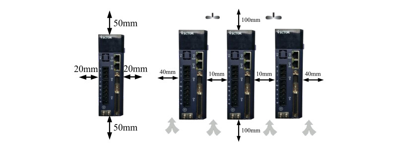
Installation Precautions
● Install the driver on a dry and sturdy platform. Maintain good
ventilation and
heat dissipation during installation and maintain good grounding.
● Please install in the specified direction to avoid malfunction.
● When installing, please ensure that the servo driver is kept at a
specified distance from the inner
surface of the cabinet and other machines, otherwise it may cause
fire or malfunction.
Installation
Environment
Requirements | Atmospheric Pressure | 86~106kPa |
| Mbient Humidity | 0~55℃ |
| Ambient Temperature | 0~90%RH |
| IP Rating | IP20 |
| Vibration | 0~4.9m/s^2 |
● When installing, do not block the suction and exhaust ports, and
do not allow foreign objects
inside the product to enter,otherwise it may cause malfunction or
fire due to aging of internal components.
● Do not place heavy objects on or under this product as this may
result in injury.
● Please install in the following environment:
1.places without direct sunlight;
2.Locations where the ambient temperature is in the range of 0 ° C
to 55 ° C;
3.Relative humidity in the range of 0% to 95%, and no condensation;
4.Locations free of water droplets, vapors, dust and oily dust;
5.Locations where there is no high heat device;
6.Non-corrosive, flammable gas and liquid sites;
7.It is not easy to splash water, oil and medicine;
8.places that are not exposed to radioactive radiation;
9.Strong and vibration-free places;
10.Locations where there is no electromagnetic noise interference.
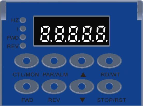
The panel contains 8 buttons and 5 digital tubes. Only 5 of the 8
buttons can be used, and the
remaining 3 buttons reserved. The general functions of the five
buttons are shown in the table below.
| Key Name | Key function |
| PAR/ALM | mode switch, return to the previous menu |
| ▲(add) | increase flashing bit value of the LED digital tube |
| ▼(dec) | Decrease flashing digit value of the LED digital tube |
| STOP/RST | Moves the blinking LED tube to the left; checks the high value of
data
longer than 5 bits; Fault reset;execute Fn function |
| RD/WT | read/write parameter values;enter fn page |
Wiring precautions
● It is recommended not to use single-phase 220V for main power
supply,
which may cause damage to electrolytic capacitor due to lack of
phase.
● Do not change the wiring during power-on, otherwise it may cause
electric
shock or injury.
● Please perform wiring or inspection by professional technicians,
otherwise it
may cause electric shock or product failure.
● Please carefully confirm the wiring and power supply. The output
circuit may be short-circuited due to
wiring errors or application of different voltages. The brake does
not operate when the above fault occurs,
which may result in mechanical damage or personal injury.
● Do not connect the input power cable to the U, V, and W terminals
of the
drive. Otherwise, the servo driver will be damaged.
● When wiring, do not pass the power cable and signal cable through
the same pipe, and do not bundle
them together. The distance between the two should be more than
30cm to avoid interference.
● The driver ground terminal must be grounded to avoid leakage and
reduce the interference of the system,
and the diameter of the ground wire should be the same as or above
the power supply line.
● When connecting the AC power supply and DC power supply to the
servo unit, connect to the specified
terminal. Failure to do so may result in malfunction or fire.
● For the wiring length, the command input line is up to 3m and the
encoder
line is up to 20m.
● Use a twisted-pair shielded cable for the signal cable and
encoder cable, and
ground the shield with a single end.
●The U, V, W terminals of the driver and the U, V, and W terminals
of the motor should be connected one by one
according to the name. If it is wrong connected, the motor cannot
operate normally.
● Common DC bus products require pressure sensitive resistors and
the wiring
is secure.
● Please check the power after the power is off for at least 5
minutes. Even if the power is turned off, high voltage
may remain inside the servo drive. Therefore, do not touch the
power terminal within 5 minutes after the power is
turned off, otherwise it may cause electric shock.
● Do not turn the power ON/OFF frequently. When it is necessary to
continuously turn ON/OFF the power, please control it once or less
in 1 minute. Since the power supply section
of the servo driver has a capacitor, a large charging current
(charge time of 0.2 seconds) flows during the ON/OFF
power supply. Therefore, if the power is turned ON/OFF frequently,
the performance of the main circuit components
inside the servo driver will be degraded.
● Do not apply power when the terminal block screws are loose or
the cable is
loose. Otherwise, it may cause fire.
● Take appropriate shielding measures in the following locations,
otherwise
the machine may be damaged:
1. Locations that cause interference due to static electricity;
2. A place that produces a strong electric field or a strong
magnetic field;
3. Locations where there may be radiation radiation;
4. A place with a power cord nearby.
Maintenance and inspection Precautions
● do not change the wiring while the power is on, otherwise it may
cause electric shock or injury.
● please perform wiring or inspection by professional technicians,
otherwise it
may cause electric shock or product failure.
● please check the power after the power is off for at least 5
minutes. Even if the power is turned off,
high voltage may remain inside the servo drive. Therefore, do not
touch the power terminal within
5 minutes after the power is turned off, otherwise it may cause
electric shock.
●when replacing the servo drive, please back up the servo driver
user parameters to be replaced before
the replacement, and transfer the backup to the new servo drive,
and then restart the operation,
otherwise the machine may be damaged.
Accessories:
| Accessory name | Image | |
| Satandard Spare Parts | Power terminal |  | Adapt to E1,E2 structure drive |
| Cn3 encoder plug | Encoder plug on the driver side |
| Cn4 control terminal plug | Input/output signal terminals,user wiring |
| Encoder connection line | The standard cable length is 3, 5, 8, 10, 13, 15 meters, according
to customer
needs Provide independent connector |
| Power line | The standard cable length is 3, 5, 8, 10, 13, 15 meters, according
to customer
needs Provide independent connector |
| Drive monitoring line | Connect and adjust the software for remote monitoring and firmware
update |
| Purchasing Spare Parts | USB to RS232 Adapter cable | If necessary, self purchase |
| Ethernet communication line | If necessary, self purchase |
Certificates
1. CE (EU Safety Standard);
2. IEC/EN61800-5-1:2007 (Safety requirements for electrical,
thermal and energy in Section 5-1 of the
variable speed electric driver system), corresponding to the
national standard GB12668.501-2013;
3, IEC / EN61800-3: 2004 + A1 (speed control electric driver system
part 3 electromagnetic compatibility
standards and its specific test methods), corresponding to the
national standard GB12668.3-2012.

Quality Checking:
Four times Production testing
Two Times 24 hoursTesting
100% Inspection Before Shipping

Delivery Time and Shipping Way
1. For small order we always can delivery out within 1 week.
2. Our products can be shippied via Air, Land or Sea.
| Packing details of Servo Drive |
| Products | E1(3-6A) | E2(7-12A) | E3(16-27A) |
| Ctn. Size | 280*208*78 | 280*208*112 | 375*290*155 |
Our Team:


